
Pumping units NB-M, NB-Mt, NB-Mg, NB-Mv, NB-Mv-E, NB-Mn, NB-Mn-E
From 420,000 ₽
In stock
The unit type NV-M is designed for operation in various branches of National Economy for pumping in stationary conditions neutral, flammable, combustible and aggressive liquids.
All pump units of NV-M type manufactured by the company are divided into 2 groups:
-pump units in version of double mechanical seal - NV-Mt (all high-pressure and low-pressure units are combined here);
-sealed units with magnetic coupling NV-Mg
All units are manufactured by TU 3631-114-00217389-2007.
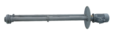
Modernised semi-submersible unit NV-M is a unit with vertical axial medium supply to the impeller of open type and with spiral medium outlet from the body through a spigot and through a pressure pipe to the base plate.
The pump (inlet, impeller, casing, spigot) is separated from the running gear by an oil chamber with double mechanical seal.
The running gear of the pump - lower and upper shafts, connected via coupling halves and sprockets, are driven by an electric motor via a coupling.
The coupling consists of an upper coupling half, coupling halves and sprockets.
The lower rotating shaft is supported by a 3309E-2Z SKF rolling bearing.
The upper rotating shafts are supported by rolling bearings 6307-2Z SKF.
The bearings do not require additional lubrication throughout their service life.
The direction of rotation of the pump shaft is clockwise when the pump is viewed from the engine side.
Shafts are located in sealed suspensions - lower suspension and upper suspensions - protective tubes with flanged connections.
Variation of the pump immersion depth is achieved by changing the length and number of upper suspensions and upper shafts.
The hermetic tightness of the suspensions is ensured by a double mechanical seal, which consists of two identically designed single mechanical seals.
The arrangement of single mechanical seals are tandem type, i.e. sequential.
The lower mechanical seal prevents leakage of the pumped medium from the pump side and is located in the oil chamber cover.
The friction pair of the lower mechanical seal is cooled by the pumped medium, which enters through a hole in the oil chamber cover from the tank and is discharged into the pump body.
The upper mechanical seal on the atmospheric side is located in the oil separation chamber and is cooled by synthetic 0W40 engine oil.
The hermetic tightness of suspensions is controlled by a float level sensor - contactless level switch PDU2.1.10-EX.
Failure of one of the mechanical seals causes leaks in the lower suspension.
When the leakage level rises to 125±3 mm from the suspension base, the RCP2.1.10-EX is activated and a signal is sent to the control panel.
Main unit indicators
| Indicator name | Indicator value | |
|---|---|---|
| NV-MV-50/80 NV-MV-E-50/80 | NV-MN-50/50 NV-MN-E-50/50 | |
| Destination indicators | ||
| Nominal flow rate, m3/sec (m3/h), not less than | 13,9ˑ10-3 (50) | |
| Nominal pressure head, m | 80(+8-4,8) | 50(+3-4) |
| Nominal synchronous pump shaft speed, sec-1 (rpm) | 50 (3000) | |
| Pump nominal power, kW, not more than | 21,8 | 12,4 |
| Technical and energy efficiency indicators | ||
| Unit efficiency, %, not less than | 50 | 55 |
| Permissible cavitation reserve NPSHr, m, not more than | 5,0 | 3,0 |
| External leakage through double mechanical seal, cm3/h (l/h), not more than | отсутствуют | |
| Structural and technological indicators | ||
| Unit weight, kg, not more than | Refer to the section Structural Indicators | |
| Overall dimensions of the unit, mm, not more than | Refer to the section Structural Indicators | |
| Notes 1 Power is given for nominal flow without taking into account immersion depth and head tolerance. 2 Allowable deviation of the unit efficiency minus 5 %. Purpose, technical and energy efficiency indicators are given for water pumping (υ=1·10-6 m2/s=1 cSt) with temperature 25°C and density 1000 kg/m3 at a barometric pressure of 1013 hPa (760 mmHg) | ||
Structural indicators
| Unit reference designation | Immersion depth, L, mm | Overall dimensions of the unit, mm, not more than | Unit weight, kg, not more than | Electric motors components | |
|---|---|---|---|---|---|
| D, mm | H, mm | ||||
| Unit NV-Mv-50/80 | 2500 | Ø860 | 3417 | 556 | A180M2, 30 kW |
| Unit NV-Mv-50/80 | 3000 | Ø860 | 3917 | 580 | A180M2, 30 kW |
| Unit NV-Mv-50/80 | 3500 | Ø860 | 4572 | 660 | A200M2, 37 kW |
| Unit NV-Mv-50/80 | 3700 | Ø860 | 4772 | 675 | A200M2, 37 kW |
| Unit NV-Mv-50/80 | 4000 | Ø860 | 5072 | 691 | A200M2, 37 kW |
| Unit NV-Mv-50/80 | 4500 | Ø860 | 5572 | 717 | A200M2, 37 kW |
| Unit NV-Mv-50/80 | 5000 | Ø860 | 6018 | 774 | А200L2, 45 kW |
| Unit NV-Mv-50/80 | 5500 | Ø860 | 6518 | 798 | А200L2, 45 kW |
| Unit NV-Mv-50/80 | 6000 | Ø860 | 7018 | 822 | А200L2, 45 kW |
| Unit nv-Mv-E-50/80 | 2500 | Ø860 | 3467 | 596 | VA180M2, 30 kW |
| Unit nv-Mv-E-50/80 | 3000 | Ø860 | 3967 | 620 | VA180M2, 30 kW |
| Unit nv-Mv-E-50/80 | 3500 | Ø860 | 4502 | 715 | VA200M2, 37 kW |
| Unit nv-Mv-E-50/80 | 3700 | Ø860 | 4702 | 730 | VA200M2, 37 kW |
| Unit nv-Mv-E-50/80 | 4000 | Ø860 | 5002 | 756 | VA200M2, 37 kW |
| Unit nv-Mv-E-50/80 | 4500 | Ø860 | 5502 | 772 | VA200M2, 37 kW |
| Unit nv-Mv-E-50/80 | 5000 | Ø860 | 6042 | 830 | VA200L2, 45 kw |
| Unit nv-Mv-E-50/80 | 5500 | Ø860 | 6542 | 853 | VA200L2, 45 kw |
| Unit nv-Mv-E-50/80 | 6000 | Ø860 | 7042 | 877 | VA200L2, 45 kw |
| Unit NV-Mn-50/50 | 2500 | Ø860 | 3407 | 497 | AIR160M2, 18.5 kW |
| Unit NV-Mn-50/50 | 3000 | Ø860 | 3907 | 522 | AIR160M2, 18.5 kW |
| Unit NV-Mn-50/50 | 3500 | Ø860 | 4367 | 582 | AIR180S2, 22 kW |
| Unit NV-Mn-50/50 | 3700 | Ø860 | 4567 | 597 | AIR180S2, 22 kW |
| Unit NV-Mn-50/50 | 4000 | Ø860 | 4867 | 610 | AIR180S2, 22 kW |
| Unit NV-Mn-50/50 | 4500 | Ø860 | 5367 | 636 | AIR180S2, 22 kW |
| Unit NV-Mn-50/50 | 5000 | Ø860 | 5917 | 696 | AIR180M2, 30 kW |
| Unit NV-Mn-50/50 | 5500 | Ø860 | 6417 | 720 | AIR180M2, 30 kW |
| Unit NV-Mn-50/50 | 6000 | Ø860 | 6917 | 744 | AIR180M2, 30 kW |
| Unit NV-Mn-E-50/50 | 2500 | Ø860 | 3467 | 537 | VA160M2, 18.5 kW |
| Unit NV-Mn-E-50/50 | 3000 | Ø860 | 3967 | 562 | VA160M2, 18.5 kW |
| Unit NV-Mn-E-50/50 | 3500 | Ø860 | 4427 | 622 | VA180S2, 22 kW |
| Unit NV-Mn-E-50/50 | 3700 | Ø860 | 4627 | 638 | VA180S2, 22 kW |
| Unit NV-Mn-E-50/50 | 4000 | Ø860 | 4927 | 650 | VA180S2, 22 kW |
| Unit NV-Mn-E-50/50 | 4500 | Ø860 | 5427 | 676 | VA180S2, 22 kW |
| Unit NV-Mn-E-50/50 | 5000 | Ø860 | 2967 | 738 | VA180M2, 30 kW |
| Unit NV-Mn-E-50/50 | 5500 | Ø860 | 6467 | 760 | VA180M2, 30 kW |
| Unit NV-Mn-E-50/50 | 6000 | Ø860 | 6967 | 784 | VA180M2, 30 kW |
| Unit NV-Mn-E-50/50 | 4200 | Ø860 | 5127 | 660 | VA180S2, 22 kW |
| Unit NV-Mn-E-50/50 | 6200 | Ø860 | 7167 | 797 | VA180M2, 30 kW |
| Unit NV-Mn-E-50/50 | 5300 | Ø860 | 6267 | 737 | VA180M2, 30 kW |
| Unit NV-Mn-E-50/50 | 3200 | Ø860 | 4127 | 549 | VA180S2, 22 kW |
| Unit NV-Mn-E-50/80 | 4200 | Ø860 | 5202 | 762 | VA200M2, 37 kW |
| Unit NV-Mn-E-50/80 | 2400 | Ø860 | 3317 | 550 | VA180M2, 30 kW |
| Unit NV-Mn-E-50/80 | 4300 | Ø860 | 5302 | 763 | VA200M2, 37 kW |
Note
- The motor can be replaced by another motor with similar parameters. It is possible to deliver without electric motor;
- The plate dimensions and immersion depth can be customised to the customer's requirements;
- The unit made of cast iron SCH 20 GOST 1412 (ver. B) or steel 20 GL GOST 21357 (ver. A) is designed for pumping neutral, flammable and combustible liquids. From steel 12H18N9TL GOST 977 (ver. K) - for aggressive liquids.
Pumped medium parameters
| Indicator name | Unit of measurement | Value |
|---|---|---|
| Temperature: minimal maximal |
˚С | minus 60 plus 80 |
| Kinematic viscosity | cSt | not more than 70 |
| Density | kg/m3 | not more than 1000 |
| Mass fraction of mechanical impurities | % | not more than 3 |
| Maximum linear particle size | mm | not more than 10 |
| Saturated vapour pressure | kPa | 66,7 |
| Impurity content: sulphur mass fraction, not more than paraffin mass fraction, not more than chloride salt concentration, not more than hydrogen sulphide content, not more than |
% % mg/l ppm |
3,5 7,0 900 100 |