
Насос НВ 50/50 - Агрегаты типа НВ 50/50
From 420,000 ₽
In stock
The unit type NV-M is designed for operation in various branches of National Economy for pumping in stationary conditions neutral, flammable, combustible and aggressive liquids.
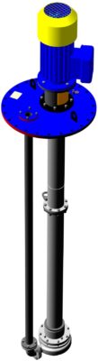
Modernised semi-submersible unit NV-M is a unit with vertical axial medium supply to the impeller of open type and with spiral medium outlet from the body through a spigot and through a pressure pipe to the base plate.
The pump (inlet, impeller, casing, spigot) is separated from the running gear by an oil chamber with double mechanical seal.
The running gear of the pump - lower and upper shafts, connected via coupling halves and sprockets, are driven by an electric motor via a coupling.
The coupling consists of an upper coupling half, coupling halves and sprockets.
The lower rotating shaft is supported by SKF rolling bearing 3309E-2Z. The upper rotating shafts are supported by rolling bearings 6307-2Z SKF.
The bearings do not require additional lubrication throughout their service life.
The direction of rotation of the pump shaft is clockwise when the pump is viewed from the engine side.
Shafts are located in sealed suspensions - lower suspension and upper suspensions - protective tubes with flanged connections.
Variation of the pump immersion depth is achieved by changing the length and number of upper suspensions and upper shafts.
The hermetic tightness of the suspensions is ensured by a double mechanical seal, which consists of two identically designed single mechanical seals.
The arrangement of single mechanical seals are tandem type, i.e. sequential.
The lower mechanical seal prevents leakage of the pumped medium from the pump side and is located in the oil chamber cover.
The friction pair of the lower mechanical seal is cooled by the pumped medium, which enters through a hole in the oil chamber cover from the tank and is discharged into the pump body.
The upper mechanical seal on the atmospheric side is located in the oil separation chamber and is cooled by synthetic 0W40 engine oil.
The hermetic tightness of suspensions is controlled by a float level sensor - contactless level switch PDU2.1.10-EX.
Failure of one of the mechanical seals causes leaks in the lower suspension.
When the leakage level rises to 125±3 mm from the suspension base, the RCP2.1.10-EX is activated and a signal is sent to the control panel.
Characteristics of the pumped medium
| Indicator name | Unit of measurement | Value |
| Temperature: — minimal — maximal |
°С | – 15 + 80 |
| Kinematic viscosity | cSt | up to 70 |
| Density at plus 15 °C | kg/m3 | from 720 to 1000 |
| Saturated vapour pressure, not more than | kPa | 66,7 |
| Impurity content: — sulphur mass fraction, not more than — paraffin mass fraction, not more than — mass fraction of mechanical impurities — maximum linear particle size — chloride salt concentration, not more than — hydrogen sulphide content, not more than |
% % % mm mg/l ррm |
3,5 7,0 3 10 900 100 |
Main unit indicators
| Indicator name | Indicator value of NV-M type unit |
|
1 Destination indicators
|
|
| Nominal flow rate, m3/ч (м3/sec), not less than | 12,5; 20; 25; 30; 50; 60 |
| Nominal pressure head, m | (15; 20; 32; 50; 80; 100; 110)-3%+5% |
| Inlet pressure, MPa (kgf/cm²), not more than | 0,1 (1,0) |
| Immersion depth (distance from the base surface of the plate to the impeller axis), mm, not more than | Standard range - 2.5; 3.0; 3.5; 3.7; 4.0; 4.5; 5.0; 5.5; 6.0 and any other on customer request |
| Nominal synchronous motor shaft speed, sec-1 (rpm) | 25 (1500); 50 (3000) |
| Power consumption, kW, not more than | Depends on the specific discharge characteristics of the pump |
|
2 Technical and energy efficiency indicators
|
|
| Efficiency factor, not less than | 35% and depends on the specific pump discharge characteristics |
| Permissible cavitation reserve NPSNR, not more than | 5.0m and depends on the specific pump discharge characteristics |
| External leakage to the environment, l/h | Negative |
|
3 Structural and technological indicators
|
|
| Unit weight, kg, not more than | Listed in Annex B |
| Overall dimensions, mm, not more than | Listed in Annex B |
| Notes 1 Purpose, technical and energy efficiency indicators are specified for water pumping (ν=1·10-6 m2/s) temperature 25 0С, density 1000kg/m3at a barometric pressure of 1013 hPa (760 mmHg) 2 The pressure referred to the baseplate is less than the pump pressure by the immersion depth and the losses in the pressure pipe. 3 The allowable cavitation margin (over and above the liquid vapour elasticity) is referred to the pump axis and is independent of the liquid temperature. |
|
Requirements for operating conditions
The unit belongs to the equipment of group II according to GOST 31441.1 and is intended for use in explosive areas of class 2 according to GOST R 51330.9, where there are explosive mixtures of category IIB according to GOST R 51330.11, group T4 according to GOST R 51330.5.
Units with flowing part made of steel are produced in climatic version UHL, category of placement 1 according to GOST 15150-69 and are designed for operation in macroclimatic regions with moderate and cold climate, cast iron - in version U, category of placement 1 and are designed for operation in macroclimatic regions with moderate climate.
The units are supplied with electric motors in general industrial version or with electric motors in explosion-proof version.
The units equipped with explosion-proof electric motors are designed for operation in zones of class B-Ig in explosive and fire-hazardous production facilities and installations in accordance with the requirements of the "Rules for electrical installations".
Overall dimensions of applied electric motors
| Overall size (height of the axis of rotation) | Installation dimension along the length of the bed | Number of poles | Number of revolutions, min-1 . | Motor length, Ldrive, mm | Weight, kg |
| 132 | M | 2 | 3000 | 418 | 95 |
| 160 | S | 4 | 1500 | 600 | 175 |
| 160 | M | 2 | 3000 | 630 | 180 |
| 180 | S | 2 | 3000 | 580 | 198 |
| 180 | M | 2 | 3000 | 620 | 221 |
| 200 | M | 2 | 3000 | 655 | 295 |
| 200 | L | 2 | 3000 | 695 | 315 |
Dimensions of the submerged part up to the rotational axis of the impeller (determined by the submerged depth)
| Immersion depth, m | 2,5 | 3,0 | 3,5 | 3,7 | 4,0 | 4,5 | 5,0 | 5,5 | 6,0 |
| Overall dimension, mm (not more than) | 2500 | 3000 | 3500 | 3700 | 4000 | 4500 | 5000 | 5500 | 6000 |
| Note: the dimensions of the standard line are given, the dimensions can be changed to any size with a multiple of 100mm upon customer's request. | |||||||||